デジタルMEMSマイクロホンの音響パラメータをテストするには、デジタル信号を直接オーディオアナライザーシステムに接続するか、別の形式(たとえば、アナログ)に変換する必要があります。品質管理(QC)テストの対象となる典型的なパラメータは、他のほとんどのマイクロホンのテストと同じです。感度、周波数応答、歪み、そして時折、信号対雑音比(SNR)が含まれます。一般的には、研究室環境で実施される完全なマイクロホンの特性評価では、EIN(等価入力ノイズ)、PSR(電源供給の拒絶比)、PSRR(電源供給の拒絶比率)、およびダイナミックレンジなどのパラメータが測定または計算されます。オプションとして、マイクロホンの方向性の挙動を異なる周波数で測定するためには、ターンテーブルを使用することができます。
デジタルMEMSマイクロホンで使われる単位は、アナログとは異なります。アナログマイクロホンの感度はmV/PaまたはdBV/Paで表されますが、デジタルマイクロホンではdBFS(デシベル・フルスケール)が使われます。デシベル・フルスケールは最大値を指し、94 dBSPL (1Pa)からデジタルマイクロホンの最大デジタル出力までがそのマイクロホンのヘッドルームになります。最大デジタル出力の値は、最大入力音圧レベル(AOP)と同じ意味で扱われます。
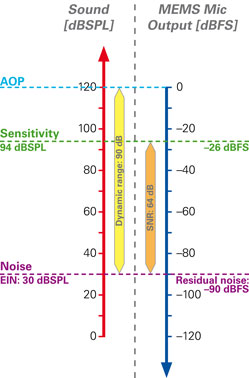
サウンドレベルとデジタルレベルの対比
単体のMEMSマイクロフォンのテストはほとんど行われません。ほとんどの場合、MEMSマイクロフォンは複数搭載されたPCB上でテストされます。PCBの性能を評価する際に注目されるのは、搭載されたMEMSマイクロフォンがお互いにどのように動作するかです。典型的なパラメータには「感度スパン」があります。これは、搭載されたMEMSマイクロフォンで測定された最高感度と最低感度の差を示します。
デジタルMEMSマイクロホンの特長
デジタルMEMSマイクロホンは、½サイクルPDMフォーマットでデータを伝送します。MEMSマイクロホンはCLK入力が必要とされ、DATAからデータを出力します。そして、二つのマイクロホンでひとつのデータラインを共有します。したがって、それぞれのマイクロホンは、右または左チャンネルに設定されます。この設定はL/R入力ピンがVddまたはグランドに接続されるかによって決まります。MEMSマイクロホンの多くは、1.8 Vまたは3.3 Vで動作します。
通常動作では、左のマイクロホンはクロック信号の各立ち上りエッジで、また右のマイクロホンは各立ち下りエッジでデータビットを書き込みます。片方のマイクロホンがデータを書き込んでいる間、 もう片方のマイクロホンはハイインピーダンスモードになり、DATA出力にデータを配置します。DSPではデータを受信し、右と左の二つの信号ストリームに分割します。
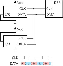
二つのデジタルMEMSマイクロホンによる通常動作
しかし、二つのマイクロホンのうち、ひとつが正しく組み込まれていないか動作していない場合はどうなるでしょう?
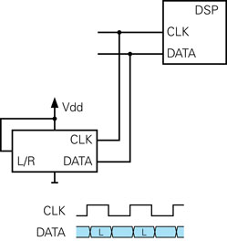
MEMSマイクロホンのひとつに不具合がある場合
この例では、右のマイクロホンが欠落しているため、データラインに書き込むのは左のマイクロホンだけです。立ち下がりのエッジでは、左のマイクロホンがDATAラインを高インピーダンス状態にするため、DATAラインは以前に左のマイクロホンによって書き込まれた状態を維持します。その結果、受信するDSPから見ると、右のマイクロホンが左のマイクロホンとまったく同じデータを提供しているように見えます。つまり、2つのデータストリームは同一です。この問題はテストシステムで対処する必要があります。MEMSアレイPCBをテストする際には、欠落したマイクロホンを検出することが基本的な機能です。
デジタルMEMSマイクロホンを動作させるために使用されるクロック周波数は通常数百kHzから3MHzまでです。低いクロックレートは低い電力消費を意味しますが、同時に音質も低くなります。
デジタル信号の安定性を確保するためには、デジタルMEMSマイクロホンとオーディオテストシステムの距離を短く保つことがおすすめです。これらのマイクロホンは単に長い高容量のケーブルを駆動するためには設計されていません。