More and more devices in the home, healthcare and industry interact acoustically with their users; smart speakers, medical ventilators, or voice alarm systems, etc. The alarm signals range from simple beeps and sirens, through standardized tone sequences or melodies, to pre-recorded or even synthetically-generated voice instructions. For the manufacturers of the devices that generate such signals, the question arises how these sometimes-complex acoustic signals can be reliably quality-controlled?
While a sound level measurement is usually sufficient for simple siren signals, for ‘speaking’ devices, such as intelligent loudspeakers, you may need a more sophisticated test system (described hereafter).
In this article, we focus primarily on the most commonly-used device type, i.e. the verification of standardized tone sequences or melodies. Specifically, we consider the alarm tones of medical devices, such as those described in the IEC 60601-1-8 standard for ventilators.
The following table shows some of these tone sequences, which, depending on the patient’s condition, refer to the current medical indication or its urgency.
| Cause |
Medium Priority |
High Priority |
| General |
c c c |
c c c - c c |
| Cardiac |
c e g |
c e g - g C |
| Artificial Perfusion |
c f# c |
c f# c - c f# |
| Ventilation |
c a f |
c a f - a f |
| Oxygen |
C b a |
C b a - g f |
| Temp / Energy delivery |
c d e |
c d e - f g |
| Drug or fluid delivery |
C d g |
C d g - C d |
| Equipment or supply failure |
C c c |
C c c - C c |
Alarm tones for medical equipment
Cardiac Medium Priority
Cardiac High Priority
Furthermore, the exact timing of these sequences is also standardized, as can be seen from the diagram below.
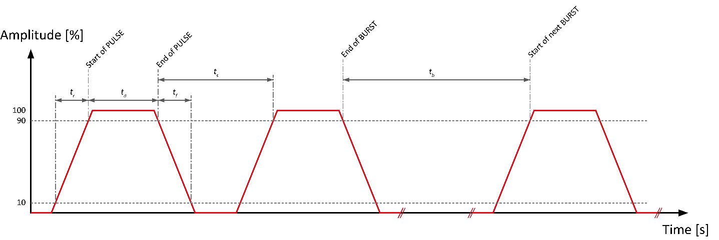
Alarm tone timing definition
Therefore, three parameters need to be verified:
- The frequency of the individual tones
- The levels of the generated tones
- The order and duration of the tones and the pauses in between
Frequencies and Levels
The simultaneous measurement of frequency and level is usually easy to achieve. This must also determine the steepness of the rising or falling edges and the duration of the individual tones.
The biggest challenge with this measurement is to get the analyzer to trigger at the start of every incoming pulse, i.e. correctly recognize the start of the sound and trigger the various measurements at the appropriate times.
The Sequence of Tones
The ordered sequence of tones must be verified. So, the measuring device must not only recognize the individual tones and measure their parameters, but also check the correctness of the sequence.
Practical Implementation
All these tasks can be completed using a programmable measuring device, with a PC or PLC as the sequence controller. For the practical implementation, we now consider two different types of measurement devices:
- A laboratory device (FX100)
- A portable acoustic analyzer (XL2)
A) Laboratory Measurement Device
Modern laboratory measurement devices, such as the FX100, have a wide range of functions that meet the above requirements, measuring the frequency and level as well as the detecting the pulse edges. These measurements are transmitted via a data interface (e.g. USB) to the controlling computer, which then calculates the desired results.
The following test setup shows such a measuring device together with the necessary accessories
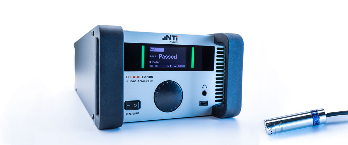
FX100 mit M2010 Microphone
There are three ways to measure:
- Clocked measurements (e.g. every 100 ms) of amplitude and frequency.
- Continuous measurement of the time signal in oscilloscope mode.
- Measurement of the signal spectrum over time.
In all three cases, the measuring system then correlates the data received with a target curve and makes a good / bad decision based on the result. The question of which of the three above measuring methods are best suited for the application at hand, or which software should control the procedure, depends on various factors. In order to carry out a correct assessment and evaluation here, an in-depth knowledge of the measuring system and experience in the implementation of industrial test methods are necessary. It is therefore advisable to search for and implement a suitable solution in close cooperation with the provider of the test system.
Example
This graph below shows the frequency-time plot of an “Escape” alarm tone according to DIN 33404 and KTA 3901 that is verified with the aid of an FX100 Audio Analyzer.
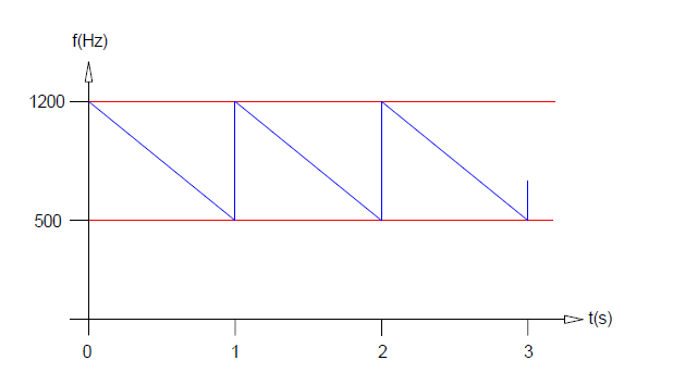
Frequency vs. Time of "Escape" alarm sound
Escape alarm tone
For the test setup, you need to connect the input of the FX100 Audio Analyzer to the amplifier output of the alarm tone generator. The test instrument is operated in the “Continuous Meter” mode, and controlled by a dedicated software package (see screenshot below).
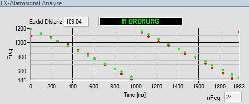
Correlation of ideal signal (green) and measured signal (red)
The measurement panel shows a plot of frequency vs. time, with an ideal escape alarm signal (green dots), and the acquired results of a measurement (red dots).
The match between the ideal data vs. the measured results is calculated by a special algorithm, the so-called “Euclidean Distance”, which is expressed by a single number. This distance is finally compared against an upper limit, thus giving the overall PASS/FAIL result.
B) Portable Acoustic Analyzer
Unlike table-top devices, most portable acoustic analyzers have a less extensive set of measurement functions. Nevertheless, some of these instruments, e.g. the XL2, are more than suitable for testing alarm tones. Specifically, the measurement device can be used to record the alarm tone and save it as a WAV file. This file can in turn be transferred to a PC and further analyzed using suitable software. The advantage of this setup is the precise determination of the signal level with the aid of a calibrated sound level measurement device.
See also:
Retrofitting a complex, safety-critical PA system for periodic testing
The paper describes considerations and the implementation of retrofitting a fully-automated procedure, for testing a public address system, into a safety-critical environment (a nuclear power plant). There are over 4000 loudspeakers, about 200 amplifiers as well as various alarm-signal generators that need to be tested every day within a few minutes. Additionally, all command room microphones are checked using a semi-automated procedure. The procedures were designed and configured to not only reliably detect single defective components, but also to not produce any false alarms.
Authors: Schmidle, Gregor; Schwizer, Philipp; Häns, Winfried
AES Paper Number 9117