How to objectively test a high-end audio system (part 1)
When talking about high-end audio systems, what comes to mind are incredible sound reproduction and reliability; an ultimate sound experience. What would we like to take for granted? That the best materials are being used. How we feel about the sound we hear is down to personal taste – a subjective judgement. On the other hand it is necessary to create objective tests that produces reliable, comparable and traceable results. This is how we do it.
In this first of two parts we’ll cover Quality Control (QC) possibilities in various processes within a speaker manufacturing environment:

Art Dèco Loudspeaker
In the second part we will take a closer look at the installation and repair & service processes:

1) R&D
The R&D phase builds the fundament of a high quality product. Any shortcomings not solved or managed at this early stage of the product development may come back and bite us at a later stage.
We examine the complete signal chain. Any unwanted noise before or within the amplifier will be audible through the loudspeakers. It is therefore essential to keep the signal clean from the very beginning of the signal chain.
a) Distortion
Unless you are a heavy rock guitarist, distortion is likely an unwanted effect and is avoided as it affects the perception of sound quality. Distortion is mainly a result of a component at any point in the signal chain reaching an upper limit of operation. Therefore tests should be performed close to these limits. The distortion can be quantified as THD (Total Harmonic Distortion), or as individual harmonic distortion values.
Some tube amplifiers produce a significant amount of even-numbered harmonic components (k2, k4, k6). Advocates argue that this creates a fuller, more pleasant sound.
Read more about Distortion here.
b) Hum & Noise
The presence of noise or hum can mask nuances in the reproduced sound. Therefore providing a low-noise circuit design is one of the most important tasks in the R&D phase. Noise can be measured with or without the presence of a test signal. In either case, it is important to realize that amplifier stages amplify both the signal and the noise. The signal needs to be much more significant than the noise. That is, a high SNR (Signal to Noise Ratio) is desired.
When using balanced analog audio channels, it is important to measure the CMRR (Common Mode Rejection Ratio) as this defines the ability to cancel out cable-inducted noise or hum. Noise, and especially hum, can also be introduced from the system power supply. Therefore it is recommended to perform tests with different mains-power conditions and settings.
Read more about balanced lines here.
c) Bandwidth
The bandwidth is measured with a frequency response measurement. The measured level has to be within the expected limits throughout the specified frequency bandwidth. Modern sound systems cover bandwidths up to ultra-sonic frequencies.
d) Linearity
All the above mentioned measurements can be influenced by the amplitude of the input signal, as well as the power of the output signal. An appropriate way to verify this system behaviour is to run an amplitude sweep signal at the system input. The amplitude shall range from zero to the maximum allowed input signal. The output signal is measured with level and distortion and shall be within the expected limits through the input signal range.
e) Channel balance and separation
The spatial awareness of the listener is based on having more than one sound source, e.g. stereo. Therefore it is vital that all channels behave as uniformly as possible. All the before-mentioned measurement results shall be compared for all channels of the system.
Furthermore the influence of one channel on other channels, e.g. caused by unwanted electro-magnetic induction or capacitive coupling, must be checked. This is done with a Crosstalk measurement.
f) Acoustic signal path
In the R&D phase, the developer has to deal with loudspeaker drivers as well as loudspeaker systems. Besides the acoustical parameters, the electrical parameters are of interest. However, before any measurement results can be assumed to be reliable, new bass and midrange loudspeakers need to be operated for a certain time in order to have the suspension material reach its final characteristics.
g) Woofer and midrange driver conditioning
Several burn-in procedures for loudspeaker drivers are known. The proposed test signals range from noise to music. Practical experience at ART DÉCO ACOUSTICS showed that a low frequency sine wave signal delivered excellent results. The loudspeakers suspension is displaced in a very controlled and predictable way, while not producing bothersome loud noise.
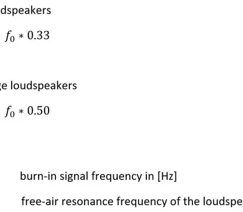
h) Burn-in signal frequency
The signal shall be at a low frequency, so that the driver suspension gets properly displaced. Also, the frequency shall have ample distance from the free air resonance frequency, so that the generator can properly control the driver.
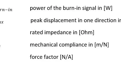
i) Burn-in signal power
The required power for exciting the loudspeaker to the desired xmax value in a controlled way can be calculated with this formula

where:
j) Burn-in duration
The goal of the burn-in process is to achieve settled and stable mechanical conditions. The required period of time to reach those conditions is different for each loudspeaker model, and therefore must be evaluated individually. A practical way to proceed is to apply the burn-in signal and measure the f_0 (free-air resonance frequency) and R_0 (free-air resonance impedance) values initially and then every two hours, until they become settled. To avoid interference with the loudspeakers thermal behavior, it is advised to allow the loudspeaker to cool off before performing f_0 and R_0 measurements.
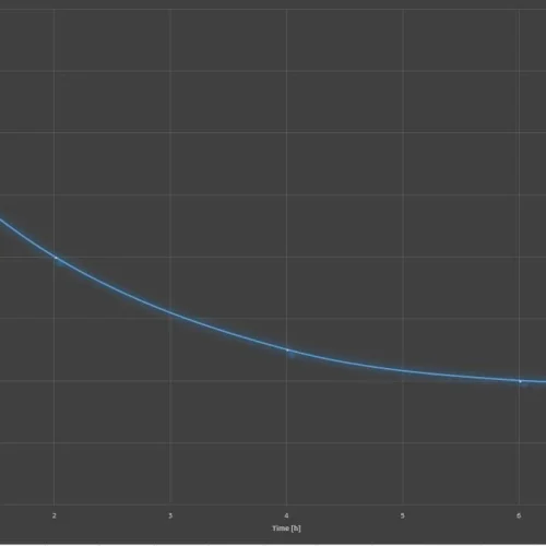
Figure 2. f_0 vs. time
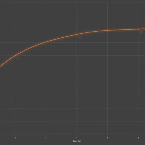
Figure 3. R_0 vs. time
Depending on the individual loudspeaker model, typical burn-in times are 6 to 36 hours for bass loudspeakers, and 6 to 24 hours for midrange loudspeakers.
k) Loudspeaker measurements
The R&D phase requires all of the classic loudspeaker measurements. The bass, midrange and high-frequency drivers are rated individually electrically and acoustically. The Thiele/Small parameters of the drivers are used to determine and optimize the loudspeakers housing dimensions. The acoustic performance of the system shows the interaction of all individual components. It is characterized by measuring frequency response, distortion response, and sensitivity. Also the directional characteristic of the complete system can be measured and optimize in the R&D phase.
All acoustic measurements must be executed in a defined and reproducible acoustic environment. The use of a calibrated measurement microphone is recommended. The microphone distance and position relative to the loudspeaker must be kept constant. In case of frequency response ripples caused by imperfections of the testing environment, a smoothing filter (e.g. 1/3 octave bandwidth) can be applied.
2) Incoming QC
a) Electrical components
IQC testing of electrical components is required when the component plays a critical role in the signal path, and the headroom of the component’s specified vs. requested accuracy is low. Quite often, these are parts used in the loudspeaker cross-over network, such as:
Inductance > inductor value, distortion vs. current, distortion vs. frequency
Capacitance > capacitor value
Depending on long term experience and significance, these tests can be either executed as sample tests (a few components from one batch delivered) or as a 100% incoming test.
b) Acoustic components
While in less sensitive markets a loudspeaker system will reach its final characteristics eventually during its normal usage, this is not an option for high-end audio manufacturers. Therefore a crucial initial procedure for all new incoming bass and midrange loudspeakers is to perform the burn-in procedure as described before.
c) Loudspeaker pairing
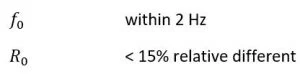
The settled results of the burn-in test can be used to place loudspeakers into groups with similar behaviour. This is important for using more than one driver of the same type in one loudspeaker, as well as building left and right loudspeaker pairs that show identical behaviour. The accepted deviation of f_0 and R_0 within the same group depends on the enclosure the loudspeaker will be used in:
3) Manufacturing QC
a) Device testing
In this stage, the individual devices of the high-end audio system are tested against their specifications.
b) Amplifier final test
The completed amplifier devices run through a thorough set of tests, such as frequency response, output power, distortion response, hum and noise rejection ratio, channel separation ratio, spectral noise analysis, channel balance, inter-channel phase, slew rate and CMRR (Common Mode Rejection Ratio). This set of tests is performed at several gain settings. Where applicable, user controls such as LEDs, switches or dial-controls are tested for mechanical and functional performance.
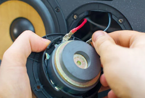
Manufacturer final assembly of Loudspeaker
c) Loudspeaker final test
The final assembled loudspeakers are tested electrically for impedance response. Special attention is paid to the device resonance frequencies and resonance impedances. The acoustic test for final assembled loudspeakers contain frequency response, distortion response, diversity, sensitivity and Rub & Buzz. The latter is especially crucial as even the slightest objectionable audible effects would not be accepted by the customer. Although each individual loudspeaker driver has already been tested for Rub & Buzz, this stage of testing reveals any noise coming from problems in the mechanical assembly of the loudspeaker, such as vibrating pieces or air leakages in sealed cavities. As in all previous acoustic test stages, it is vital to have a test fixture that allows reproducible results with minimum influence from outside noise.
d) Acceptance limit finding
The applied limits for passing or failing a measurement have to be calculated for each individual measurement function. Whenever possible, absolute limits evaluated from a component’s datasheet are preferred. However, some measurement functions are not suitable for absolute limits. This is often the case for acoustic measurements such as Rub & Buzz when either no specification is available, or the acoustic conditions during test are different than those used for specification.
For such measurement functions, one or several reference measurements are taken and overlain with a headroom. The amount of headroom depends on the number of references taken, and the allowed mean variation.abrA
e) System testing
Finally, the individual devices get put together to the final system configuration. In this final stage, the test depth can be reduced as the individual system devices are already thoroughly tested. The interaction between amplifier, left and right loudspeaker is tested with a few simple acoustic sensitivity and frequency response measurements. At this point, it is also appropriate to perform a subjective listening test at a defined listener position, listening to material that is familiar to the hearer (a favorite song).
Continue reading with part II.