This article is devided into two parts. In this first article, you will learn about the design and preparation of the test and the test environment. The second article covers system calibration & maintenance.
1. What to consider?
There are many possible reasons for variations in measurement results within a single production line. They can be caused by:
- Fluctuations in quality of subcomponent material
- Changes in the manufacturing and assembly process
- Variance in environmental influences
Defining appropriate measurement parameters and functions for the end-of-line test lays out the groundwork for an efficient test system. Especially when it comes to comparing results across several production lines. Further reasons for unwanted deviations are operator handling errors and wear and tear of test system components such as electrical contacts. Another important topic is a recovery plan in case of an IT disaster, such as the loss of a hard drive.
The following paragraphs contain summarized and essential information and focus on the most important steps you should follow.
2. What and how to measure?
There are two fundamental, yet conflicting requirements to fulfill:
- The test must be as detailed as necessary to reliably test the desired quality.
- The test must be fast enough to ensure no bottleneck in production.

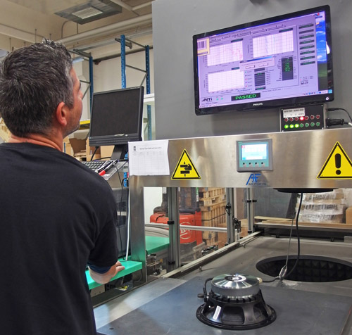
A factory worker at Eighteen Sound during the QC Stage. Credits: AudioXPress
Typical measurement functions, for example in a passive loudspeaker end-of-line test, are frequency response, impedance response, harmonic distortions in various configurations, sound pressure levels at different frequency bands, resonance frequency, Thiele/Small parameters, speaker polarity, and, of course, a Rub & Buzz measurement.
Technically, all those measurements can be executed by a single glide-sweep stimulus signal. However, in many test applications it is required to execute some measurement functions, such as frequency response, sound pressure level and all electrical measurement, with the nominal level of the tested device, whereas the Rub & Buzz test is typically executed at a higher level. Besides considering the measurement function, it is also necessary to set the test signal levels high enough for a proper signal to noise ratio above environmental noise, but also low enough to not damage the hearing of the test system operator. The latter can be diminished by suppressing the test level at higher frequencies to which the human ear is more susceptible.
For loudspeakers, the start and stop frequencies of test signals must not only cover the transmission band of the loudspeaker, but also adequately include the resonance frequency. If the DC resistance of the driver is determined by an extrapolation of the impedance response, it is advised to set the lower frequency far enough away from the resonance. Start and stop frequency of the Rub & Buzz test signal is typically set to the low frequency range of the loudspeaker in order to trigger any electro-mechanical problems.
3. Defining good and bad
Defining limits for testing an acoustic device can be more challenging than you might have thought. There are various methods and strategies. The first major decision to be taken is whether to work with absolute limits or to use one or several reference samples. The following diagram illustrates the decision process.

Generic limit calculation decision tree
The limit-finding strategy should be evaluated for each measurement function separately.
Typical measurement functions that are suitable for the application of absolute limits are frequency and distortion response, as well as all electrical measurements such as impedance response and its derivate results. When using absolute limits for acoustic measurements, it is important to know the conditions under which the limits are valid (e.g. free field). If the conditions in the end-of-line test are different, the measurement result must be corrected accordingly.
Usually reference samples are only used when no specification is available, e.g. for Rub & Buzz.
4. Test environment
The ideal test environment is an anechoic chamber. However, for most this is not feasible. The other option is to build a box for the test jig. This must be built from solid wood, asymmetric and shielded with acoustical foam inside. Since test jigs usually are not commercially available off the shelf, most manufacturers build their own.

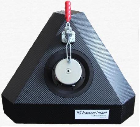
Tetrahedral Test System for Loudspeaker Testing, by Hill Acoustics Limited.
While building one box is a manageable task, problems often start when it comes to building more than one comparable test jigs. It is recommended to accurately document all measures, materials and building processes, as even minor variations can produce measurable differences in the acoustic results.
Nonetheless, the test jig has to fulfill certain characteristics while testing:
- Place the Device Under Test (DUT) i.e. the loudspeaker, in a defined position relative to the measurement microphone.
- Fix the DUT to the test jig tightly.
- Create a reproducible acoustic situation.
- Avoid acoustic reflections.
- Provide defined front and/or back cavities in the test jig for the DUT
- Shield the microphone from background noise.
- Shield the microphone from structure-borne noise i.e. vibrations in the microphone stand.
- Shield the operator from high sound pressure exposure.
- Allow efficient loading and unloading of the DUT (manual or automated).
- Allow reliable wiring of the DUT, with correct polarity (manual or automated).
- Allow for quick retooling of the jig for testing different models.
Furthermore, the test jig itself should not introduce noise with resonating walls or rattling parts.
5. Testing with multiple lines and locations
Frequently, there are several production lines of the same type within one factory. Sometimes, the production lines are in different factories and even in different parts of the world. Yet, it is still desired to manufacture and also test the product in exactly the same way. The products shall be tested with the same test parameters, against the same limits, and, of course, deliver the same quality and yield.
Most of the components in different end-of-line test systems can be:
- easily chosen to be identical
(Audio analyzer & accessories, cables & contacts)
- parameterized to behave identically
(Audio amplifier gain, microphone sensitivity)
However, the test jigs have to be built as identically as possible, since they directly influence the acoustic behavior. Although there are mathematical corrections available to overcome minor deviations of the test jigs, these corrections massively increase the complexity of the system.
When limit calculation is based on reference samples, it must be considered that the physical reference samples are only available on one site. The calculated limits though are applied on multiple lines and sites, mostly without access to the physical reference.
6. Data logging and traceability
Almost every loudspeaker manufacturer, especially when using a Quality Control management system, is required to be able to trace back the end-of-line test results of their products. On high-quality loudspeakers this might be for every single loudspeaker by using a serial number reference. On smaller and cost-effective devices, mostly the batch number is available. This typically allows tracing back the factory location, manufacturing date and production line number.
For the data logging, this means that the end-of-line test software must be able to log several complementary data besides the measurement results, such as date & time, calendar week, project name, operator name, serial or batch number as well as environmental data like temperature and humidity.
Obviously, those log files can become quite large over time. Therefore, it is recommended to periodically start new log files e.g. every week, or at the start of each new production batch.
Links relevant to this topic: