Let`s clear up some things about Sweeps
Sweeps are a popular method in the field of audio measurement to describe the change in a measured output value over a progressing input parameter. The most commonly-used progressive input parameter is frequency varied over the standard audio bandwidth of 20 Hz to 20 kHz. But there is much more to a sweep. This article provides an overview as well as detailed explanations of various methods, parameters and optimizations concerning sweeps.
Definitions
When sweep measurements are plotted on a graph, the y-axis identifies the measurement results. The graph is named according to what is being measured appended with the word “response”. For example, results can be named as “amplitude response”, “impedance response” or “phase response”. An exception to this naming convention is the term “frequency response”. To be technically correct, the frequency response refers to both the amplitude and the phase response together. Be aware that it is, however, also common in practice that the frequency response refers to the amplitude response alone.
Frequency Response
The input signal could be varied across frequency or amplitude (x-axis). The convention is that, in the absence of further information, it may be assumed that frequency is used as the variable input for the x-axis.
The following section describes how the sweep input signal can vary and how these variations can be parameterized.
Glide Sweep
A glide sweep (or chirp) is a continuous signal in which the frequency increases or decreases logarithmically with time. This provides the complete range of testing frequencies between the start and stop frequency. An advantage over the stepped sweep is that the signal duration can be reduced by the user without any loss of frequency resolution in the results. This allows for rapid testing.
The impulse response of a device under test can be calculated from the measured results. From this the amplitude, phase, and distortion measurements are calculated. Unwanted acoustic reflections can be reduced using a time window.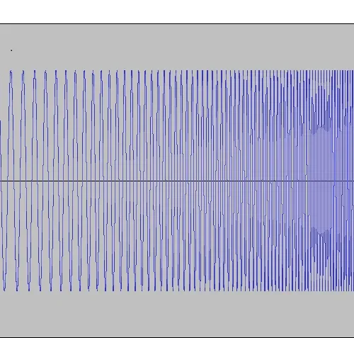
Glide Sweep signal
Since the exact duration of the sweep signal is known, the glide sweep is ideally suited for measuring signals that are not played by the audio test system itself, rather by the device under test. To indicate to the measurement system that the test signal is about to start, the sweep signal is preceded by a short trigger sequence. This method is particularly useful when measuring devices which do not have an audio input channel, e.g. Smartphones, tablets or smart devices.
Although the theory behind the glide sweep has been known for several decades, its use in audio measuring devices has only evolved over the past several years. The reason for this lies with the high computing power required.
Stepped Sweep
In a stepped sweep, one variable input parameter (frequency or amplitude) is incremented or decremented in discrete steps. After each change, the analyzer waits until a stable reading is detected before switching to the next step. The scaling of the steps is linear or logarithmic. The stability condition (settling) can be defined by the user.
Since the settling time of different test objects cannot be predicted, the duration of a stepped sweep cannot be determined exactly in advance.
For the determination of amplitude or frequency response, the stepped sweep has been largely replaced by the glide sweep. The main application for the stepped sweep is to measure the linearity of systems. Here, the frequency of the test signal is kept constant while the amplitude is varied. Typically the amplitude and distortion of the device under test are measured. This is also referred to as an “amplitude sweep”.
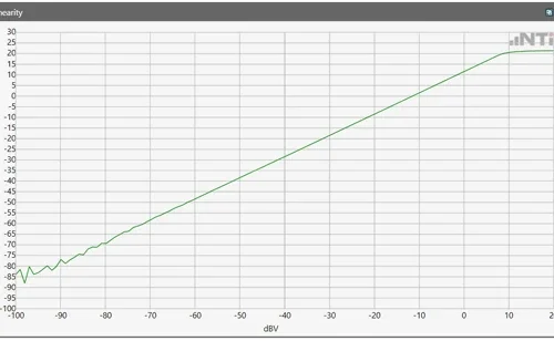
Linearity measurement
Amplitude Weighting
With frequency selected as the variable input parameter, the amplitude profile of the input signal can be defined. For example, this allows for the equalization of an amplifier or loudspeaker so that a flat electrical or acoustic amplitude response is achieved as output. This method can be applied to both glide sweep and stepped sweep.
Time Sweep
In the case of a time sweep, the x-axis represents time. Again the y-axis represents a measured value, e.g. amplitude. The change in the measured value is observed over time. For example, how does the response of the device under test change over a long period?
Table Sweep
A rarely-used special form of the stepped sweep is the table sweep. Here the input signal is produced from a table as a sequence of any frequency and amplitude pairs.
Practical applications
Audio and acoustic devices and systems are operated throughout the audible range and beyond. This range extends over the two dimensions of frequency and level. Accordingly, measurements on audio and acoustic systems must measure and evaluate the relevant parameters in these dimensions. The basic measurements used are sweep measurements.
For a meaningful and accurate measurement, the most important sweep parameters to be defined are the start and stop values for the frequency or amplitude as well as the steps (number of desired measuring points) or the duration of the measurement (in the case of a GlideSweep).
Measurements on acoustic components
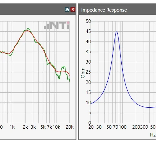
For sweep measurements on acoustic components, such as loudspeakers, several items have to be considered. Apart from the acoustic frequency response in dBSPL (left), the impedance frequency response (right) may also be interesting. The start and stop frequencies must therefore be selected so that not only the specified response bandwidth of the speaker is covered, but that the sweep also begins far enough below the resonance frequency.
The duration of the GlideSweep depends on the start frequency. The lower the frequency, the longer the electromechanical system has to be excited. In the following measurement of a midrange speaker, 1.5 seconds of signal duration was used for a measurement bandwidth of 20 Hz – 20 kHz.

Frequency response
The measurement was carried out in non-free-field conditions. The resulting reflections appear in the frequency response (green curve) in the form of ripples. These are removed by a sliding curve averaging (red curve). Alternatively, the reflections can also be eliminated by the use of a time window.
Measurements on playback devices
Playback devices are identifiable by the absence of a closed signal path. i.e. It is not possible to play a test signal generated by the audio generator directly into the device while simultaneously reproducing the signal as an output from the device. Without this closed loop, the audio analyzer cannot synchronize with the signal. Typical examples of playback devices are mobile phones or tablet computers, as well as most devices with built-in speakers.
For these devices, the GlideSweep test signal is recorded and pre-loaded on the device as a wav or mp3 file for playback and analysis. To overcome the lack of synchronization between the audio generator and the analyzer, the GlideSweep test signal can be preceded by a short audible trigger, at a fixed interval before the sweep signal, that is recognized by the analyzer.
When the trigger is detected by the audio analyzer, the measurement starts automatically. Since the duration of the GlideSweep is known, the analyzer is exactly synchronized with the test signal being played.
0:00 /0:00
Measurements on playback devices
Measurements on audio devices
These are devices with analog or digital audio inputs and outputs, e.g. Amplifier or mixing console. A closed-loop input and output connection to the audio generator and analyzer is possible. This example measures a microphone input stage of an audio mixer. Amplitude and distortion across the audible frequency range are measured with a 500 ms fast GlideSweep of 20 Hz – 20 kHz. The output level and distortion as a function of the input level is measured with an amplitude sweep in the range of -100 dBV to -20 dBV.
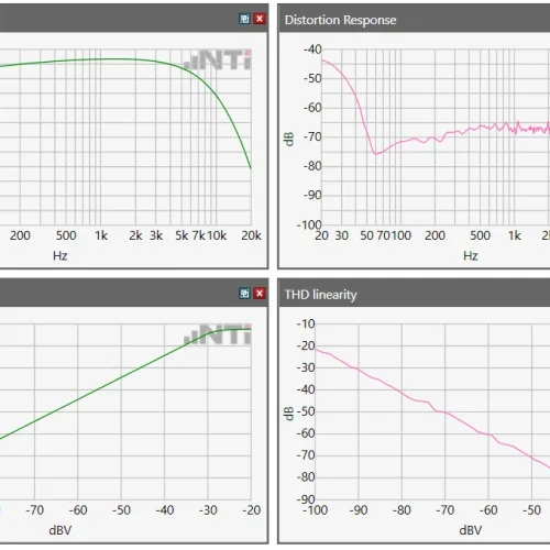
Particular attention is needed on systems with dynamic control behavior, such as Automatic Gain Control (AGC) or level limiter. In this case, to ensure that the system under test is in a stable state before the actual measurement, the sweep signal is prefixed with a “pre-tone” with, for example, 1 second duration.
0:00 /0:00